 By
By 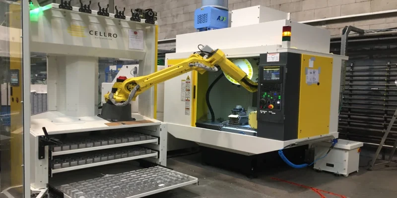
The pressure on the modern machine shop floor is relentless. When production schedules are tightly packed, the idea of halting operations to deploy a new automation system can feel like an unacceptable gamble. Plant managers often find themselves caught in a paradox: you need to automate to increase throughput and solve labor shortages, but you cannot afford the immediate drop in capacity required to install the equipment.
Overcoming this hurdle requires shifting away from traditional, highly invasive system integration. By focusing on modular, flexible technologies, engineering teams can implement robust machine tending automation while keeping existing production cycles running smoothly.
1. Shift to Floor-Mounted Collaborative Systems
Traditional robotic automation typically involves heavy industrial arms anchored to the floor, surrounded by expansive safety fencing, light curtains, and interlock systems. Installing these setups requires structural drilling, extensive wiring, and significant floor space modification, meaning your machine tool sits idle for days or weeks.
Deploying collaborative robots (cobots) or lightweight, mobile industrial units provides a less disruptive alternative. Because these systems often feature integrated power management and force-limiting safety sensors, they require a much smaller footprint.
- Zero-Anchor Mounts: Utilizing heavy-duty, high-friction mobile bases allows engineers to roll the automation unit right up to the machine interface without drilling into the plant floor.
- Dual-Mode Operation: A properly integrated system allows a human operator to manually load parts from one side while the robot is being calibrated on another, ensuring zero lost time during physical alignment.
2. Prioritize Off-Site Programming and Simulation
A common source of unexpected downtime during automation deployment is debugging robot trajectories, part-gripping cycles, and collision avoidance on the live shop floor. Every minute spent writing code or adjusting waypoints at the physical machine tool is a minute of lost production.
To mitigate this, utilize digital twin simulation software. By building a complete virtual model of the CNC machine, raw stock material fixtures, finished part trays, and the robotic arm, automation engineers can program and validate the entire handling sequence virtually.
- Pre-baked Trajectories: Programs are written, optimized, and stress-tested for kinematic reach limitations or singularities before the physical hardware ever arrives at the facility.
- Offline Deployment: When physical integration day arrives, the pre-tested code is simply uploaded via USB or network protocols, reducing onsite commissioning from weeks to a single shift.
3. Implement Non-Invasive Machine Interfacing
Wiring an automation system directly into an older CNC machine’s main electrical cabinet can void warranties, risk logic errors on the main board, and require extensive diagnostic downtime. Instead, look for application kits that utilize standardized, external communication methods.
Rather than splicing directly into the internal PLC ladder logic, focus on clean boundaries of control:
- Standardized I/O Interfaces: Utilize standard external M-codes or Ethernet-based industrial communication protocols to handle the handshake between the machine and the handler (e.g., “cycle complete” and “door open” signals).
- Pneumatic and Mechanical Retrofits: Install external pneumatic door openers and auto-vices that operate independently of the main machine controller. This bypasses the need to modify complex internal circuitry, meaning the machine tool can continue cutting metal using manual door operation right up until the final handoff signal is verified.
4. Leverage Unified, Modular End-Effectors
A major bottleneck during system commissioning is configuring the end-of-arm tooling (EOAT). Designing, machining, and plumbing custom grippers on-site adds unpredictable delays to your timeline.
Opting for ecosystem-compatible, all-electric or plug-and-play pneumatic grippers drastically cuts down physical installation time. Modern smart grippers feature integrated quick-change mechanisms and standardized software drivers that run directly inside the robot’s teach pendant. This allows engineers to switch from handling round bars to flat plates without re-engineering the entire fluid power distribution or rewiring physical sensor lines.
The Phased Implementation Blueprint
Minimizing risk during a deployment comes down to separating physical installation from logic validation. By treating the upgrade as a series of independent steps rather than a single massive overhaul, you ensure the shop floor maintains its baseline output.
| Phase | Core Objective | Impact on Current Production |
|---|---|---|
| Phase 1: Digital Design | Build the digital twin and run full kinematic cycle simulations offline. | 0% – Purely software-based preparation. |
| Phase 2: Peripheral Prep | Install external pneumatic chucks, parts trays, and quick-change tooling fixtures. | Minimal – Can be completed during scheduled preventive maintenance windows. |
| Phase 3: Roll-in & Handshake | Position the mobile base, connect the standardized I/O cables, and load pre-tested software programs. | Low – Typically requires a single shift for physical alignment and final safety validation. |
By breaking the integration down into these distinct, non-invasive steps, engineering teams can transition a legacy CNC cell into a fully automated, high-yield asset without breaking the continuity of their ongoing production schedules.


Comments